
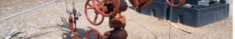
All wells are capped by an assembly of steel pipe and fittings known as the wellhead. The wellhead’s function is to contain the reservoir or well fluid and to allow safe access to the casing and tubing for the life of the well. A wellhead is made up of a series of components that are connected and sealed in various ways. In this section, the following key components of a wellhead (from bottom to top) are covered. Bear in mind not every wellhead requires all of these components since the need for each depends on the type of well, the well completion, and expected operation.
- Casing Head
- Casing Spool
- Casing Hangers
- Packoff Flange
- Tubing Head
- Tubing Hanger
- Tubing Head Adaptor
- Christmas Tree
CASING HEAD
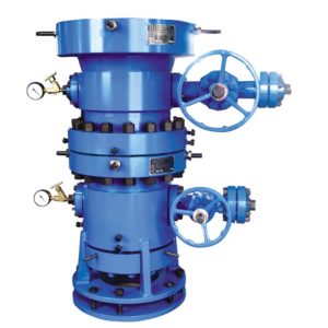 The casing head, also referred to as a casing bowl, is the lowest part of the wellhead assembly. The bottom of the casing head is configured to attach to the casing below (typically, the surface casing). The upper inside of the casing head provides a bowl in which the next casing string can be set and sealed (if required). The top of the casing head then connects to the next wellhead component. Access to the annulus between the surface casing and the next casing string is available through side outlets. The function of the casing head is to:
- Isolate the inside of the surface casing from the outside environment.
- Provide a platform for and a means to test the rig BOP stack during drilling and well servicing operations.
- Support or transfer the weight of drilling and work over equipment during drilling and well servicing operations.
- Allow for suspending and packing off the next casing string (i.e., intermediate or production casing). This is accomplished by setting a casing hanger and seal against the recessed profile machined into the upper inside surface (bowl). The hanger often is held in place by lockdown screws and the seal thus formed against the casing string is called the primary seal.
- Provide access to the surface inner casing annulus for monitoring and fluid return purposes. Access to the annulus is available through side outlets drilled through the casing head.
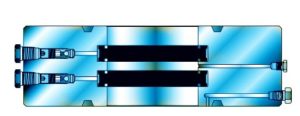
CASING SPOOLS
If a well includes one or more intermediate casing strings between the surface and production casing, the next 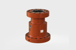 component required after the casing head is the casing spool. The bottom of the casing spool mounts on top of a casing head or previous spool, and the top connects to the next spool or tubing head assembly. The spool is designed so the bottom bowl or counter bore will allow a secondary seal to be set on the previous casing string, while the top bowl will hold a casing hanger to suspend and allow a primary seal around the next string of casing. Multiple casing spools may be used, one on top of the other, to hang intermediate casing strings and the final production casing string. The function of the casing spool assembly is to:
- Allow for a secondary seal on the previous casing string in the counter bore. With a secondary seal in place, flange or hub seals and casing hanger seals are isolated from internal casing pressure.
- Provide a port for pressure testing primary and secondary casing seals and flange connections (see below “Primary and Secondary Seals” in 5.1.3.10.2 Seal Types).
- Provide a platform to support, seal and pressure test the BOP during drilling and well servicing operations.
- Provide a load shoulder and controlled bore in the top bowl to support the next casing hanger and enable a primary seal for the next intermediate or production casing.
- Provide annular access for fluid returns or fluid injections and pressure monitoring, through side outlets drilled in the spool assembly.
CASING HANGERS
Both casing heads and casing spool assemblies may require the use of casing hangers. Casing hangers attach to the end of a given casing string and suspend and seal the casing string in the top bowl of a casing head or spool. Casing hangers come in two main varieties: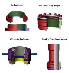
- Slip type hangers that are installed around the casing after it is run, either before or after the casing is cemented into place. Slip type casing hangers are used as a contingency when pipe is stuck, allowing the casing to be cut off and set where it sits.
- Mandrel type hangers that are threaded onto the casing. Mandrel type casing hangers provide superior well control when landing the hanger and improve the annular seal.
The function of the casing hanger is:
- To suspend the load of the casing string from the casing head or spool.
- To center the casing in the head.
- To provide a primary seal against the inside of the casing head and isolate the casing annulus pressure from upper wellhead components.
PACK OFF FLANGE
 A packoff flange is rarely used. It is set above a casing head or spool assembly and also sealed against the intermediate or production casing to enable a safe increase in pressure rating between the casing head or spool and any wellhead equipment above the flange, for example, a tubing head. It is also known as a “restricted packoff flange” or “crossover flange”. A packoff flange may also be used in temporary operations such as pressure testing primary seals or as a safety device when drilling out the cement that remains in the shoe joint (or “float collar”)
TUBING HEAD
The tubing head assembly provides a means to suspend and seal the production tubing in the wellhead. The tubing 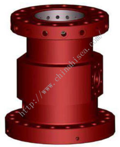 head is the top spool in the wellhead assembly and is installed after the last casing string is set. The bottom of the tubing spool includes a counterbore that can be used to set a seal against the production casing. The top of the tubing head provides a landing shoulder and a seal bore for landing and enabling a seal to the tubing hanger. Above the tubing head is the tubing head adaptor which provides a transition to the Christmas tree. The function of the tubing head assembly is to:
- Enable the suspension of the tubing.
- Allow for sealing the annulus between the tubing and the production casing.
- Allow access to the annulus between the tubing and production casing, through side outlets.
- Provide a means to support and test the service rig BOP during well completions.
- Provide a bit guide for running the tubing without causing damage to the production casing.
With certain varieties of tubing heads, it also functions to:
- Allow a secondary annulus seal to be set around the top of the production casing.
- Provide access for a test port to test primary and secondary seals.
- Ensure safe running and retrieving of tubing hangers in high pressure operations (e.g., snubbing operations).
- Allow for correct orientation of equipment to enable running multiple tubing strings.
Tubing heads come in three basic connection configurations. Well type and conditions are used to determine which type of tubing head is most appropriate for the operation.
- Top connection threaded
- bottom connection threaded
- welded.
TUBING HANGER
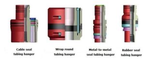 A tubing hanger is also commonly known as a dog nut. A tubing hanger typically is threaded onto the top of a tubing string and is designed to sit and seal in the tubing head. Usually the tubing hanger is run through the BOP and landed in the top bowl of the tubing head. The top of the tubing hanger provides a profile necessary for the lock screws that will secure the hanger in the tubing head.
- In a simple, single string completion the hanger carries the weight of the tubing and the tubing is “hung in neutral”.
- In other completions where the tubing–casing annulus must be isolated from the fluid handled (e.g., produced water injection or disposal wells), different intervals must be isolated from each other, or gas will be injected to enhance fluid production (i.e., in a gas lift well), hanger design must also consider the use of a downhole packer where the tubing may be set in compression, tension or neutral, and upward (compression) forces may be placed on the tubing string during production or injection operations.
- Tubing hanger design / hold downs also should consider the dynamic loads that can be applied in artificial lift wells by the reciprocating motion of a rod string and torque induced at the start-up and shut-down of ESPs and PCPs.
TUBING HEAD ADAPTOR
The tubing head adaptor provides a transition from the tubing head to the Christmas tree. With a basic tubing head configuration where the tubing hanger is seated in the top of the tubing head, the bottom of the tubing head adaptor will seal against the tubing head and contain reservoir or injection fluids moving through the top of the tubing. With an extended neck tubing hanger, the adaptor will provide a secondary seal against the hanger, isolating the seal between tubing head and adaptor and any lock screws holding the tubing hanger in place. As such, this configuration provides a means to test the primary and secondary seals on the tubing hanger.
The following animation video narrates the different features of the well head components and the Christmas tree.
CHRISTMAS TREE
A Christmas tree is an assembly of gate valves, chokes and fittings included with the wellhead during well completion. The Christmas tree provides a means to control the flow of fluids produced from or fluids injected into the well, at surface. While Christmas trees come in a variety of configurations based on a number of well design and operating considerations, typically the bottom connection of the tree matches the top connection of the tubing head adaptor and these are generally installed as a unit, immediately after production tubing is suspended.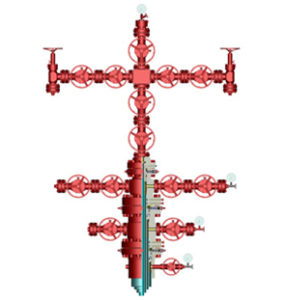
Typical Christmas tree components on a flowing, gas lift, or injector well include:
- A minimum of one master valve that will control all flows to and from each tubing string. Upper Master Valve (UMV) is used on moderate to high pressure wells as an emergency shut in system. Lower Master Valve (LMV) utilized on all Christmas trees for contingency to the UMV to shut off well flow in the event of a leaking UMV or the connection between them.
- A tee or cross leading to control valves such as production gate valves, surface safety valves, flow control valves or chokes
- Flow Wing Valve (FMV) permits the passage of well fluids to the choke. The choke valve is used to restrict control or regulate the flow of hydrocarbon from the well.
- Killing Wing Valve (KWV) is used for equalization and permits entry of kill fluid in to the compression string.
- Potentially a swab valve above the tee that permits vertical access to the wellbore.
- A tree cap that might be fitted with a pressure gauge. The tree cap provides quick access to the tubing bore for bottom hole testing, installing down hole equipment, swabbing, paraffin scraping, and other thru-tubing well work.
A Christmas tree may be modified based on well operating conditions, fluids produced and recovery methods. In the case of an assisted lift well that requires a rod string to run through the Christmas tree, the configuration is adjusted as follows:
- The master valve is either removed or incapacitated to prevent accidental closure.
- The addition of a polished rod BOP that can be closed around the polished rod to seal fluid and pressure in the wellhead if required. The polished rod BOP may be activated either manually or hydraulically.
- The addition of a stuffing box that provides a seal around the moving polished rod during operations.
- The inclusion of an environmental BOP that seals across the tubing bore in the event a polished rod breaks and is pulled or ejected out of the stuffing box. It may be integrated into the stuffing box itself or be installed as a separate component above or below the stuffing box.
Information Source
This whole article is compiled by reproducing information from Minimum Wellhead Requirements – Industry Recommended Practice. The copyright for this Industry Recommended Practice is held by Enform, 2012.
Image Credit: Double Stage Casing Head / Casing Spool / Pack-off Flange / Tubing Head, Casing Hanger, Tubing Hanger