
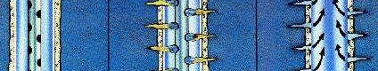
While drilling a well the side wall of the drilled hole cannot stay as is, Hence a hollow metal pipe is inserted in to the drill hole called “CASING” to protect and support the well stream.In addition to protection from the sides of the well caving in, the casing protects the well stream from outside contaminants such as any fresh water reservoirs from the well that is producing. The casings are fabricated in sections or joints that are usually 40 feet long and joined together (screwed) to form longer lengths called casing strings. Each end of the casing section has male threads. The casing sections are joined together using a collar or coupling which is slightly larger in diameter having female threads. Guide shoe and centralizes are attached to the casing to help position the casing in the center of the well.
TYPES OF CASING
Conductor Casing – is the widest type of casing installed first, usually prior to the arrival of drilling rig. Hole is often drilled with a small auger drill. Usually 20 to 50 feet long. Installed to prevent the top of the well from caving in and to help in the process of circulating the drilling fluid up from the bottom of the well. The conductor casing is 16 to 20 “in Diameter for onshore wells while for offshore wells the conductor casing is usually 30 to 42”.
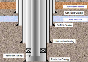
Surface Casing – is the next type of casing to be installed. It can be anywhere from a few hundred to 2000 feet long. This is smaller in diameter (13 3/8”) than the conductor casing. Primary purpose of surface casing is to protect fresh water zones near the surface of the well from being contaminated by leaking HC or salt water from deeper underground. Serves as a conduit for drilling mud returning to the surface and helps protect the drill hole from being damaged during drilling.
Intermediate Casing is usually the longest section of casing found in a well, and its diameter is 9 5/8” necessary on longer drilling intervals where necessary drilling mud weight to prevent blowouts may cause a hydrostatic pressure that can fracture shallower or deeper formations. Purpose is to minimize the hazards that come along with sub surface formations that may affect the well. Casing placement is selected so that the hydrostatic pressure of the drilling fluid remains at a pressure level that is between pore pressure and fracture pressures. These include abnormal U/G pressure zones, U/G shale, and formations that might otherwise contaminate the well, such as U/G salt deposits. Serves as insurance against the possibility of such a formation affecting the well.
Production Casing – alternatively called the oil string or long string is installed last and is the deepest section of casing in a well. This is the casing that provides the conduit from the surface of the well to the petroleum producing formation. Size depends on a number of considerations, including the lifting equipment to be used, the number of completions required and the possibility of deepening the well at a later time.
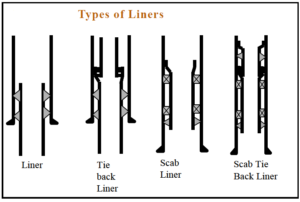
Liner Casing are sometimes used instead of intermediate casing to reduce cost. It may typically be 7”. Liner stings are commonly run from the bottom of another type of casing to the open well area. However these are usually attached to the previous casings with hangers instead of being cemented in to place. Different types of liners in use include the following:-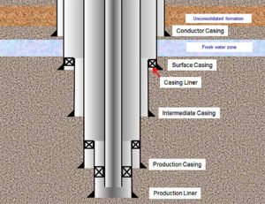
- Drilling liner – same as intermediate casing which overlaps the existing casing by 200 to 400 ft to isolate troublesome zones and to permit drilling below these zones without problems.
- Production liner – same as production casing and is run to provide isolation across the production or injection zones.
- Tie-back liner – is connected to the top of the liner with a specially designed connector and extends to the surface to convert liner to a full string of casing.
- Scab liner –is a section of casing sealed with packers at the top and bottom, used to repair existing damaged casing.
- Scab tie-back liner – is a section of casing extending upwards from the existing liner however does not reach the surface. These are commonly used with cemented heavy wall casing to isolate salt sections in deeper portions of the well.
TUBING
The pipe centered in the annulus of an oil and / or gas well through which the hydrocarbons flow to the surface from the formation is called tubing. Tubing sizes are important, too small may restrict the production and hence the profitability. However too large the tubing can reduce fluid velovity and allow for buildup of produced water that can kill the well. Large tubing also affect the economics of the project adding to the cost of the overall well design.
CEMENTING
The small space between the casing and the untreated sides of the well is filled with cement to permanently set the casing in place. The primary purpose of oil and gas well cementing is for zonal isolation, hydraulic seal (to prevent undesirable fluid coming up to surface), protect casing and hold casing & completion string. Prior to cementing, the casing is filled with water to prevent the differential pressure causing caving in of the casing. The following are accessories used during the cementing process.
Float Shoe & Float Collar : Float shoe along with an integral check valve is attached to the bottom of the casing string to prevent reverse flow the slurry in to the casing. The float shoe also guides the casing in the center of the bore hole. Float collar is installed near the bottom of the casing string. Cement plugs land on it during the primary cementing operation. Float collars are similar to float shoe, the internal check vales may be flapper type or spring loaded. The check valve prevents the back flow of the cement slurry when the pumping is stopped. Greater the cement slurry density causes the reverse flow or u tube effect of the cement.
Scratchers & Centralizers: Scratchers are used for cleaning mud and mud filter cake off the well bore wall to ensure good contact and bonding between the cement and the well bore wall. This is a simple device consisting of a band of steel that fits around a joint of casing and stiff wire fingers or cable loops attached to the band in all directions. For the scratchers to be effective the casing movement has to be either reciprocal or rotary. Centralizers are devices fitted with a hinged collar and bow springs to keep the casing or liner in the center of the well bore to ensure efficient placement of a cement sheath around the casing string.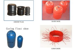
Dry cement is mixed with additives to adjust the properties of the dry cement to fit the conditions of the well bore. The common additives include accelerators (Calcium Chloride), retarders (wood pulp, hydroxycarboxylic acid and cellulose derivatives) and density adjusters (bentonite and pozzolans). Accelerators are used to increase the speed of the setting time while retarders are used to do the opposite to prevent premature setting in deep high temperature wells. Density adjusters increase the weight of the cement to reduce the cement pumping pressures or to permit higher cement column without fracturing the formation.
The cement and additive mixture is blended with water to prepare a slurry to be pumped in to the hole for cementing. The slurry is pumped in to the hole with the aid of the slurry pumping pressure to fills in the annulus between the casing and the side walls of the bore hole. A rubber plug used to separate the cement slurry from other fluids reducing contamination to maintain predictable slurry performance. Two types of plugs are commonly used viz., the bottom and the top plug. The bottom plug is launched ahead of the cement slurry to minimize the contamination of cement by fluids inside the casing prior to cementing. A diaphragm in the plug body ruptures (by increasing the slurry pumping pressure) to allow the cement slurry to pass through after the plug reaches the landing collar. The top plug has a solid body that provides positive indication of contract with the landing collar and bottom plug through an increase in slurry pump pressure. The top plug is drilled further to continue the casing operation.
The following video provide an overview of casing and cementing.
WELL COMPLETION
Once the design well depth or TD is reached, the formation must be tested and evaluated to determine whether the well will be completed for production or plugged and abandoned..This is the process in which the well is enabled to produce safely oil and or gas. It is the process of making a well for production or injection. This involves preparing the bottom of the hole to the required specification running in the production tubing and its associated down hole tools as well as perforating and stimulation as required.
The major criterion for the design of completion includes Profitability, Flexibility and Simplicity. PROFITABILITY provides production optimization and minimize operating cost over its life, FLEXIBILITY for handling current and future problems and SIMPLICITY to allow the most efficient installation and maintenance activities. The types of COMPLETION to be used depend on the characteristics and location of the Hydrocarbon formation. The types of completion are generally classified as follows:-
- Open Hole Completion
- Conventional Perforated Completion
- Sand Exclusion Completion
- Permanent Completion
- Multiple Zone Completion
- Drainhole Completion
Open Hole Completion is most basic type used in formation that are unlikely to cave in. It consists of simply running the casing directly down into the formation leaving the end of the piping open without any protective filter. This designation refers to a range of completions where no casing or liner is cemented in place across the production zone. The zone might be left entirely bare but some sorts of sand control and or flow control means are usually incorporated. Popular for horizontal drilling where cemented installations are more expensive and technically more difficult.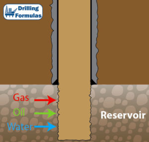
Conventional Perforated Completion consist of production casing being run through the formation. The sides of this casing are perforated, with tiny holes along the sides facing the formation, which allows for the flow of hydrocarbons into the well hole, but still provides a suitable amount of support and protection for the well hole. The process of perforating the casing involves the use of specialized equipment designed to make tiny holes through the casing, cementing, and any other barrier between the formation and the open well. In the past, ‘bullet perforators’ were used, which were essentially small guns lowered into the well. The guns, when fired from the surface, sent off small bullets that penetrated the casing and cement. Today, ‘jet perforating’ is preferred. This consists of small, electrically-ignited charges, lowered into the well. When ignited, these charges poke tiny holes through to the formation, in the same manner as bullet perforating.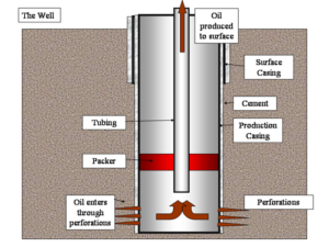
Permanent Completion: are those in which the components are assembled and installed only once. Installing the casing, cementing, perforating, and other completion work is done with small diameter tools to ensure the permanent nature of the completion. Completing a well in this manner can lead to significant cost savings compared to other types.
Multiple Zone Completion is the practice of completing a well so that hydrocarbons from two or more formations may be produced simultaneously, yet separately. For example, a well may be drilled that passes through a number of formations as it descends; alternately, it may be more effective in a horizontal well to add multiple completions to drain the formation efficiently. Although it is common to separate multiple completions so that the fluids from the different formations do not intermingle, the complexity of achieving complete separation can present a barrier. In some instances, the different formations being drilled are close enough to allow fluids to intermingle in the well hole. When it is necessary to prevent this intermingling, hard rubber ‘packing’ instruments are used to maintain separation among different completions. 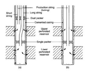
Drainhole Completions are a form of horizontal or slant drilling. This type of completion consists of drilling out horizontally into the formation from a vertical well, providing a ‘drain’ for the hydrocarbons to empty into the well. In certain formations, drilling a drainhole completion may allow for more efficient and balanced extraction of the targeted hydrocarbons. Drainhole completions are more commonly associated with oil wells than with natural gas wells.
Info Compiled From:Naturalgas.Org / Slideshare
Image Credit:
Casings, Multiple Zone & Open Hole completion: Drillingformulas.com
Perforated Completion: Oilandgastechnologies.wordpress.com